
Technical Articles & Industry Resources

TRANSFORMER ENGINEERING BLOG

Insights, Technical Guides & Manufacturing Innovations from AFP Transformers Corp.

0%

Castblock Transformers are dry-type transformers built with windings sealed inside solid epoxy insulation. Unlike oil-filled units, they use no liquid dielectric. This makes them useful in hospitals, commercial buildings, tunnels, ships, and industrial rooms where fire safety and low maintenance matter.

The operating principle is straightforward. Incoming alternating current enters the primary winding. Magnetic flux then travels through the laminated steel core. That flux induces a different voltage in the secondary winding. The cast epoxy supports the coils, limits moisture penetration, and helps resist vibration. Heat still matters. Cooling channels, resin quality, load patterns, and installation space affect real performance.

Transformer specialist Martin Heathcote has often stressed a practical point: “A transformer is only as reliable as the system around it.” That view fits Castblock Transformers well. Their resin insulation is strong, but it cannot correct poor ventilation, loose connections, dust buildup, or repeated overloading. Small details decide service life.

The technology is not flawless. Resin can age under severe thermal stress. Repairs may also be more difficult than repairs on some conventional designs. This deserves attention.

A careful evaluation should examine voltage ratio, rated power, insulation class, temperature rise, short-circuit strength, noise, and site conditions. Manufacturers may use different casting methods and testing standards. Therefore, product claims should be checked against certified test reports and installation requirements. The following guide explains how Castblock Transformers are constructed, how energy moves through them, and where their practical advantages become most visible.
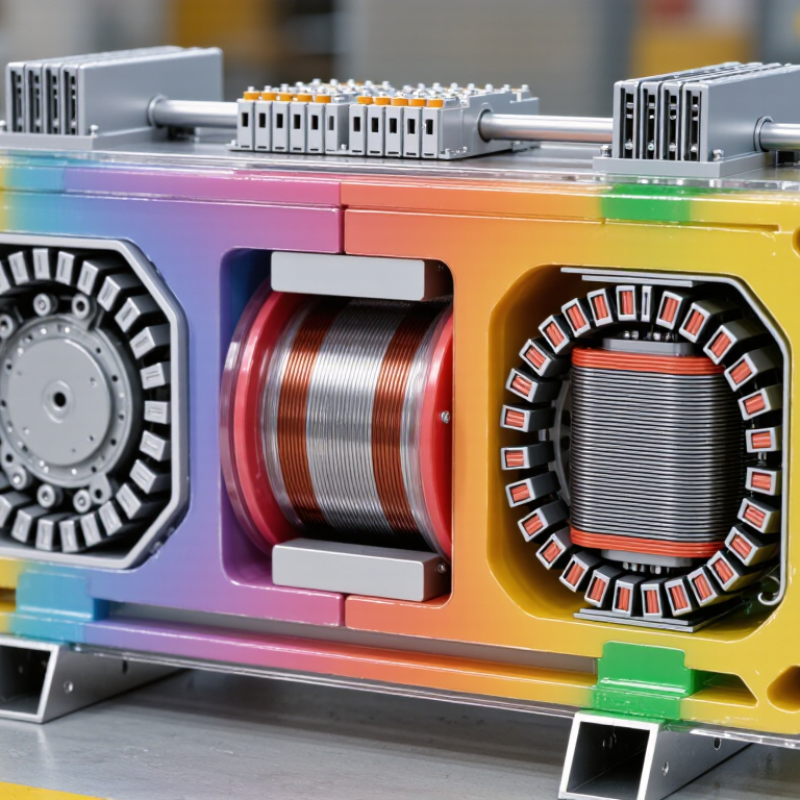
What Are Castblock Transformers and How Do They Work?

Definition and Purpose of Castblock Transformers

Castblock transformers are dry-type transformers with windings sealed inside solid epoxy resin. The resin forms a compact cast block around copper or aluminum conductors. It provides electrical insulation, mechanical support, and protection from dust and moisture. Unlike oil-filled units, these transformers use no liquid insulation. Their purpose is clear: change voltage safely near buildings, factories, transport systems, and other critical loads.

Inside the unit, alternating current creates magnetic flux in a laminated steel core. That flux induces voltage in the secondary winding. The voltage ratio follows the turns ratio between the windings. Heat travels through the resin, then moves into the surrounding air through the enclosure. This design suits indoor installations and areas with strict fire-risk controls. The U.S. Department of Energy estimates that distribution transformer losses represent about 2.5% of national electricity consumption. Better efficiency therefore matters. The IEA’s Electricity Grids and Secure Energy Transitions report says annual grid investment may need to rise from about 400 billion dollars to 600 billion dollars by 2030. Castblock units can support this expansion, although their higher purchase cost deserves careful review.

Tips: Check the rated load, insulation class, cooling method, noise level, and installation altitude. Confirm compliance with IEC 60076-11 or the applicable local standard. Keep ventilation paths clear. Resin is strong, but it is not immune to thermal cycling, partial discharge, or poor installation. That assumption needs testing. A site survey should examine humidity, dust, harmonics, and future load growth before selection.

Core Components and Structural Design

Castblock transformers use a solid, cast insulating system around their windings. This structure replaces liquid insulation with hardened resin and reinforced materials. The main components are the magnetic core, high-voltage winding, low-voltage winding, insulation layers, terminals, and protective enclosure. Each part has a defined electrical and mechanical role.

The core usually consists of stacked steel laminations. These thin sheets reduce eddy-current losses and guide magnetic flux efficiently. Around the core, copper or aluminum windings carry electrical energy between voltage levels. Cast resin surrounds the windings, filling gaps and limiting movement during short-circuit stress. It also protects the conductors from moisture, dust, and surface contamination. Strong, but not perfect.

The enclosure supports safe airflow and protects the assembly from accidental contact. Ventilation channels help remove heat produced during normal operation. Sensors may monitor winding temperature and trigger alarms when heat rises too far. Terminals connect the transformer to incoming and outgoing circuits, while grounding points control fault-current paths. In practical inspections, engineers check resin surfaces for cracks, discoloration, and unusual discharge marks. A small surface defect can signal deeper thermal or mechanical stress. Still, visual inspection alone can miss internal weakness. Electrical testing and temperature records provide stronger evidence. Structural design must balance insulation strength, cooling performance, vibration resistance, and service access. That balance is often harder than the drawings suggest.

How Castblock Transformers Operate Step by Step

A cast-block transformer is a dry-type transformer with windings sealed inside solid insulating resin. Its operation begins when alternating current enters the primary winding. The current creates a changing magnetic field in the iron core. This field travels through the core and reaches the secondary winding. Voltage then appears in the secondary coil through electromagnetic induction. The turns ratio controls whether the transformer increases or reduces voltage.

The process is continuous. Current leaves the secondary winding and supplies connected equipment. Electrical resistance creates heat in the windings and core. Heat moves through the resin and escapes from the outer surfaces into surrounding air. Cooling depends on clean ventilation and correct installation spacing. The cast resin also limits moisture entry, supports the coils, and reduces movement during short-circuit forces. It is not magic. Poor airflow still raises temperature.

During commissioning, technicians check voltage, insulation resistance, connections, and protective settings. They may also listen for unusual vibration and measure operating temperature. A cast-block design needs no liquid filling, but it still requires inspection. Dust can cover cooling surfaces, while loose connections can create dangerous hot spots. The step-by-step model is helpful, yet it leaves out real site conditions. Load changes, room temperature, and harmonics can alter performance. In practice, reliable operation comes from matching the transformer to the load and maintaining clear airflow. Further testing may be needed when readings appear inconsistent.

What Are Castblock Transformers and How Do They Work? — How Castblock Transformers Operate Step by Step
Step Transformer Part or Action What Happens Electrically Typical Technical Data Why the Step Matters
1 Incoming AC supply reaches the primary winding Alternating voltage is applied to the high-voltage or primary winding, creating an alternating magnetomotive force in the magnetic core. Frequency: 50 or 60 Hz
Common primary voltage classes: up to 36 kV
The primary winding establishes the magnetic field required for energy transfer.
2 Magnetic core produces alternating flux The laminated ferromagnetic core guides magnetic flux through a low-reluctance path. The changing flux induces voltage in both windings. Core material: laminated electrical steel
Core losses include hysteresis and eddy-current losses.
Laminations reduce circulating eddy currents and improve efficiency.
3 Cast insulation surrounds the windings The windings are encapsulated in a solid insulating compound, commonly an epoxy-based resin system. The cured material provides electrical insulation and mechanical support. Insulation type: solid cast resin
Cooling classification: commonly AN (air natural)
Encapsulation helps protect the windings from moisture, dust, vibration, and many surface contaminants.
4 Voltage is induced in the secondary winding The alternating core flux induces a secondary voltage according to the transformer turns ratio. Ideal voltage relationship: V₁/V₂ ≈ N₁/N₂
Example: a 10:1 turns ratio produces approximately a 10:1 voltage ratio.
The turns ratio determines whether the transformer steps voltage up or steps it down.
5 Load current flows through the secondary winding When a load is connected, secondary current flows. The primary draws additional current to balance the ampere-turns and transfer power through the core. Apparent power: S = V × I for single-phase systems
Three-phase apparent power: S = √3 × V × I
This electromagnetic transfer allows the load to receive power without a conductive connection between the windings.
6 Losses generate heat Winding resistance creates copper loss, while the core produces no-load loss. Additional stray and dielectric losses may occur. Copper loss: Pcu = I²R
Total efficiency for many distribution transformers is typically above 95%, depending on rating and loading.
Heat must be removed to keep winding and insulation temperatures within their rated limits.
7 Natural air cooling removes heat Heat travels through the cast insulation to the transformer surface and is released to the surrounding air by convection and radiation. Cooling method: air natural
Forced-air fans may increase short-term capacity on suitably designed units.
Clear airflow paths and correct installation spacing help prevent thermal derating.
8 Insulation system controls electric stress Solid resin insulation separates conductors and distributes electric-field stress. Proper design limits partial discharge within the insulation system. Partial-discharge performance is verified by applicable routine or type tests.
Insulation coordination considers power-frequency and impulse withstand levels.
Reliable insulation reduces the risk of internal breakdown and extends service life.
9 Voltage adjustment compensates for supply variation Tap links or an off-circuit tap changer can alter the effective turns ratio when the transformer is de-energized. Common adjustment range: approximately ±2.5% to ±5%
Tap operation must follow the equipment instructions.
Voltage adjustment helps maintain the required secondary voltage under changing supply conditions.
10 Protection and monitoring supervise operation Protective devices detect abnormal current, excessive temperature, earth faults, or other unsafe conditions and disconnect the transformer when necessary. Typical functions: overcurrent, short-circuit, earth-fault, temperature monitoring
Alarm and trip settings depend on the design and installation.
Protection limits damage to the transformer and connected electrical system.
11 Routine inspection confirms safe performance Technicians check terminals, connections, ventilation, resin surfaces, temperature indicators, earthing, and signs of tracking or mechanical damage. Checks may include: winding resistance, insulation resistance, turns ratio, earth continuity
Testing must be performed by qualified personnel.
Regular inspection can identify loose connections, overheating, contamination, or insulation deterioration before failure occurs.
12 Power is delivered continuously to the load As long as the applied voltage, frequency, load, temperature, and protection conditions remain within their ratings, the transformer transfers energy continuously. Service life depends on loading, ambient temperature, thermal cycling, insulation quality, and maintenance.
Maximum load must remain within the nameplate rating.
Operating within rated limits provides dependable service and minimizes accelerated insulation aging.
Note: Actual voltage ratings, insulation levels, impedance, temperature-rise limits, enclosure requirements, and testing procedures vary by transformer design and the applicable electrical standards.

Key Advantages and Practical Applications

What Are Castblock Transformers and How Do They Work?

Castblock transformers use windings sealed inside solid epoxy resin. The resin provides electrical insulation and protects coils from dust, moisture, and chemical exposure. During operation, alternating current creates a magnetic field in the core. This field transfers energy between windings while changing voltage levels.

Their main advantage is safer indoor operation. Castblock units contain no liquid oil, so fire and leakage risks are reduced. They also need less routine maintenance in dusty factories, underground stations, hospitals, and commercial buildings. The International Energy Agency’s Electricity 2024 report expects global electricity demand to grow by about 3.4% annually through 2026. Reliable, space-efficient equipment will matter more as facilities add cooling, automation, and charging loads. That matters.

Efficiency is another practical benefit. The U.S. Department of Energy reports that distribution transformers account for roughly 2.5% of total U.S. electricity consumption. Small efficiency gains can therefore reduce long-term operating losses. However, castblock transformers are not perfect. Resin systems can be heavier, and poor ventilation may accelerate thermal aging. Repairs are also less straightforward than replacing damaged liquid insulation. Engineers should check heat dissipation, short-circuit strength, sound levels, and local installation rules before selection. In my experience, the best result comes from matching the transformer to its environment, not choosing the most compact model automatically. That compromise deserves attention.

What Are Cast-Block Transformers and How Do They Work?

Cast-block transformers are dry-type transformers in which the windings are encapsulated in solid epoxy resin. The resin provides electrical insulation and mechanical protection, while heat is transferred through air to the surrounding environment.

The chart shows common distribution voltage levels used with cast-resin dry-type transformers. Low-voltage systems commonly operate around 0.4 kV, while medium-voltage applications frequently use 6.6 kV, 11 kV, 20 kV, or 33 kV. Because these transformers contain no insulating oil, they are widely considered for indoor facilities, public buildings, tunnels, renewable-energy installations, and industrial plants where reduced fire and spill risk is important.

Maintenance, Limitations, and Safety Considerations

Castblock transformers are dry-type units with windings sealed in solid resin. This cast insulation protects coils from dust, moisture, and mechanical movement. Heat travels through the resin and surrounding air, rather than through liquid oil. During operation, electrical energy creates a magnetic field in the core. The windings then transfer power between voltage levels through electromagnetic induction. The design is quiet, clean, and suitable for indoor installations.

Maintenance still requires discipline. Technicians should inspect ventilation paths, terminals, supports, and resin surfaces regularly. Look for cracks, darkened areas, unusual odor, loose connections, or rising temperatures. Dust can block cooling channels and create unnecessary thermal stress. Infrared scans can reveal hot connections before visible damage appears. However, cast resin is not indestructible. Severe overloads, repeated short circuits, poor ventilation, and moisture may damage the insulation. Repairs can also be difficult because the windings are permanently encapsulated. A clean enclosure does not guarantee a healthy transformer.

Safety depends on controlled work practices. Only qualified personnel should open panels or perform electrical tests. The transformer must be isolated, locked out, and verified de-energized before inspection. Grounding, correct clearances, and suitable protective equipment remain essential. Never rely on sound or temperature alone.

Tips:

Keep air inlets clear and record temperature readings over time. Tighten connections only when safely isolated. Investigate small changes early. In practice, maintenance schedules are sometimes too optimistic, so adjust them after reviewing site dust, load patterns, and operating history.

FAQS

What is a castblock transformer?

It is a dry-type transformer with windings sealed inside solid epoxy resin. The resin surrounds copper or aluminum conductors. It provides insulation, support, and protection from dust and moisture.

How does a castblock transformer change voltage?

Alternating current creates magnetic flux inside a laminated steel core. That flux induces voltage in the secondary winding. The voltage relationship follows the winding turns ratio.

Where are castblock transformers commonly installed?

They suit buildings, factories, hospitals, underground stations, and transport facilities. Indoor locations often benefit most. They are useful where fire-risk controls are strict.

Why can these transformers be safer indoors?

They contain no liquid insulation. This reduces leakage and liquid-related fire risks. However, safer does not mean risk-free. Poor wiring, overheating, or blocked ventilation can still cause problems.

Do castblock transformers require much maintenance?

They usually need less routine maintenance than liquid-filled units. There is no oil level to inspect or replace. Technicians should still check connections, temperature, noise, and ventilation paths.

Are castblock transformers energy efficient?

They can reduce operating losses when properly selected and loaded. Small efficiency improvements matter across long operating periods. Efficiency is not automatic. Oversizing, harmonics, or poor cooling can weaken the result.

What should engineers check before choosing one?

Check rated load, insulation class, cooling method, sound level, and installation altitude. Review humidity, dust, harmonics, and future load growth. Confirm the applicable electrical standard. The compact model is not always the best model.

What are the main limitations of castblock transformers?

Epoxy systems can be heavier than expected. Thermal cycling and partial discharge may age the resin. Repairs can be less straightforward after winding damage. That assumption needs testing.

Conclusion

Castblock Transformers are electrical transformers built with windings and insulation materials embedded in a solid cast resin block. Their main purpose is to transfer electrical energy between voltage levels while providing reliable insulation, mechanical strength, and protection from moisture, dust, and other environmental factors. Core components typically include primary and secondary windings, magnetic cores, cast resin insulation, terminals, cooling surfaces, and protective enclosures. This compact structure supports safe installation in commercial buildings, industrial facilities, renewable energy systems, and distribution networks.

During operation, alternating current enters the primary winding and creates a changing magnetic field in the core. This field induces a corresponding voltage in the secondary winding, allowing energy to be delivered at the required voltage. Castblock Transformers offer low maintenance, strong fire resistance, reduced environmental sensitivity, and dependable performance. However, they still require proper ventilation, periodic inspection, load monitoring, and clean connections. Their limitations may include higher initial cost, heat-management requirements, and difficult repair if internal components are damaged. Correct sizing, professional installation, and adherence to electrical safety procedures are essential.

Alexander

Alexander

Alexander is a seasoned marketing professional with a deep expertise in our company’s innovative product offerings. With a keen eye for market trends and consumer insights, he plays a pivotal role in shaping our marketing strategies and enhancing brand visibility. Alexander's passion for our core......